Magnetic field: The region surrounding
a magnet, in which the force of the magnet can be detected, is
called a field.
Magnetic field lines: There are many lines
forms around a magnet, which are originated from north pole and it seems to end
with south pole of magnet such line are known as magnetic field lines.

Properties of magnetic field lines:
(i) The magnetic field lines emerge from
north pole and merge at the south pole.
(ii) Inside the magnet, the direction of
field lines is from its south pole to its north pole.
(iii) The magnetic field lines are closed
curves.
(iv) The magnetic field is
stronger, where the field lines are crowded.
(v) Two field lines do not intersect/cross
each other.
Magnetic field lines do not intersect
each other:
This is so, magnetic field lines do not
intersect each other. If they did, it would mean that at the point of
intersection, the compass needle would point towards two directions, which is not
possible.
Magnetic field around a current-carrying
conductor:
· An electric current through
a metallic conductor produces a magnetic field around it.
· When a current carrying
conductor is kept over a compass and parallel to its needle, when the
direction of flowing of electric current reversed the deviation of compass is
in opposite direction.
· If the current is
increased, the deflection also increases.
· The magnitude of the
magnetic field produced at a given point increases as the current through
the wire increases.
· When we place the
compass at a farther point from the conducting
wire, the deflection in the needle decreases.

Right-Hand Thumb Rule:
Imagine that you are holding a
current-carrying straight conductor in your right hand such that the thumb
points towards the direction of current. Then your fingers will wrap
around the conductor in the direction of the field lines of the magnetic
field. This is known as the right-hand thumb rule. This rule is also known
as Maxwell’s
corkscrew rule.

Magnetic Field due to a Current through
a Circular Loop:
The magnetic field produced by a
current-carrying straight wire depends inversely on the distance from it.
Similarly at every point of a current-carrying circular loop, the
concentric circles representing the magnetic field around it would become
larger and larger as we move away from the wire.
Properties of magnetic field line of a
current through acircular loop:
(i) At the center of this loop the magnetic
field lines are a straight line.
(ii) Every point on the wire
carrying current would give rise to the magnetic field appearing
as straight lines at the center of the loop.
(iii) Section of the wire contributes to
the magnetic field lines in the same direction within the loop.
· The magnetic field produced
by a current-carrying wire at a given point depends directly on the
current passing through it.
· if there is a circular coil
having n turns, the field produced is n times as large as that produced by a single
turn. This is because the current in each circular turn has the same
direction, and the field due to each turn then just adds up.
Solenoid
A coil of many circular turns of insulated copper wire
wrapped closely in the shape of a cylinder is called a solenoid.

Magnetic Field due to a Current in a
Solenoid: When
electric current is passes through a solenoid, It's one end behaves as a
magnetic north pole, while the other end behaves as the south pole.

Properties of the field lines inside the
solenoid:
· The field lines inside the
solenoid are in the form of parallel straight lines.
· This indicates that the
magnetic field is the same at all points inside the solenoid. Therefore,
the field is uniform inside the solenoid.
· The field lines inside the
solenoid are in the form of parallel straight lines. This property is used to
make an electromagnet.
· A strong magnetic field
produced inside a solenoid.
Electromagnet:
A magnet is made by magnetic field produced
inside a solenoid using magnetic materials like soft iron is called an
electromagnet.

Some properties of electromagnet:
1. The magnetic field produced is generally
very strong.
2. The strength of the magnetic-field can be controlled by controlling
various factors such as the current and the number of turns in the
solenoid.
3. The polarity of the magnet can be changed by reversing the direction of
current while magnetic field is being produced by solenoid.
Differences between electromagnet and
parmanent magnet:
Electromagnet
|
Permanent magnet
|
1. The magnetic field produced is
generally very strong.
|
1. Generally the magnetic field produced is low and
moderate.
|
2. The strength of the magnetic-field
can be controlled by controlling various factors such as the current and the
number of turns in the solenoid.
|
2. The strength of the magnetic-field of
a permanent magnet is permanent but changes (decreases) with the temperature.
|
3. The polarity of the magnet can be
changed by reversing the direction of current.
|
3. The polarity of the magnet can not be
changed.
|
4. Normally soft iron is used for making
electro magnets.
|
4. Cobalt, steel etc., are used for the
purpose.
|
FORCE ON A CURRENT-CARRYING CONDUCTOR IN
A MAGNETIC FIELD:
GYAN KENDRA
|
When a a strong
horse-shoe magnet is placed in such a way that the rod lies between
the two poles with the magnetic field directed upwards. For
this the north pole of the magnet is kept vertically below and south
pole is kept vertically above the aluminium rod. When a current is passed
through the aluminium rod from end B to end A. It is observed that the rod is
displaced. It is also observed when the direction of current flowing is
reversed through rod the direction of displacement is also reversed.

Conclusion:
(i) A magnetic field exerts a force on
a magnet placed in the vicinity of the conductor.
(ii)A force is exerted on the
current-carrying aluminium rod when it is placed
in a magnetic field.
(iii) The direction of force is also reversed
when the direction of current through the conductor is reversed.
(iv) The direction of force acting on the
current-carrying rod gets reversed when
the direction of current is reversed.
(v) The force on the conductor depends upon
the direction of current and the direction of the magnetic field.
The force on the conductor:
The force on the conductor depends upon the
flowing two things:
(i) The direction of current and
(ii) The direction of the magnetic field.
·
Fleming's left-handrule:
According to this rule, stretch the thumb, forefinger and middle finger of your left hand such that they are mutually perpendicular. If the first finger points in the direction of magnetic field and the second fingerthe direction of current, then the thumb will point in the direction of motion or the force acting on the conductor.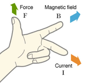
Electrical generator is based on the
principle of electromagnetic induction. It convert mechanical energy into electrical
energy.
Advantages of Alternate Current (AC) over
Direct Current (DC)
Electric
power can be transmitted to longer distances without much loss of energy.
Therefore cost of transmission is low.
In
India the frequency of AC is 50Hz. It means after every 1/100 second it changes
its direction.
Domestic Electric Circuits :
Devices that use current-carrying conductors
and magnetic fields:
Electric motor, electric generator,
loudspeakers, microphones and measuring instruments etc.
Magnetism in medicine:
MRI: The magnetic field inside the body
forms the basis of obtaining the images of different body parts. This
is done using a technique called Magnetic ResonanceImaging (MRI).
Propertie of magnetic field inside the body:
· Magnetic field is produced
in our body which travels along the nerve cells.
· This nerve impulse produces
a temporary magnetic field.
· These fields are very weak
and are about one-billionth of the earth’s magnetic field.
· Human heart and brain are
two organs which produce magnetic field.
Electric Motor:


An electric motor is a device which converts
electric energy into mechanical energy.
Uses of Electric Motor: Electric fans,
mixers, grinders, blenders, cutters, DVD players, computers, washing machines
etc.
Principle of Electric Motor: An electric Motor works on
the principle that a current carrying conductor
experiences a force when placed in a magnetic field. If the direction of
the magnetic field and that of the direction of current which pass through the
magnetic field are mutually perpendicular then the direction of the
force is given by Fleming’s left-hand rule.
(A) Split rings: These
are cylindrical shape metalic rings which are divided into two
halves. The inner sides of these halves are insulated and
attached to an axle.
Role of split rings in Electric Motor:
It works as commutator in electric motor that
reverses the direction of the flowing of electric current.
Commutator: Commutator is a device which is used to
reverse the direction of the flowing of electric current.
(B) Armatures: It is a rectangular
coil which has a large number of turns of thin insulated copper wire turned
over a soft iron core. The armature is placed between the two poles of the
field magnet such that the arm AB and CD are perpendicular to the
direction of the magnetic field.
Role of armature in Electric Motor:
(i) The armature operates by rotating
along with a magnetic field.
(ii) The armature will rest when the
resultant field is aligned with the stator (or static) field.
(C) Axle: Axle is a rotating rod like
structure which is situated in the centre of armature and split rings are
fitted on it.
The properties of commercial motors: Commercial motors are
powerful motors. Due to following properties these are powerful.
(i) Electric magnet is used in commercial
motor in spite of permanent magnet.
(ii) No of turns of insulated copper wire is
more in current carrying coil.
(iii) Soft iron crode is used to wrap the
coil, by which power is increased.
Electro Magnetic
induction
Electro Magnetic Induction: The process, by
which a changing magnetic field in a conductor induces a current in another
conductor, is called electromagnetic induction.
· The discovery of
electromagnetic induction was by made Michael Faraday.
· The induced current is found to be the
highest when the direction of motion of the coil is at right angles to
the magnetic field.
Using of a moving magnet can be
produced/induced electric current by this discovery of Faradey.
Inducing Electric current:
When we place a moving magnet inside a coil, there
produces electric current in the coil's circuit. which can be shown in
Galvanometer by deflection of it's needle. The motion of magnet with respect to
coil induces a induced potential difference, due to which flows induced
electric current in circuit.
The method to induce electric current in a
coil:
(i) we can induce current in a coil either by
moving it in a magnetic field.
(ii) By changing the magnetic field around
it.
(a) First Experiment “Self Induction”
In this experiment, when the north pole of bar magnet is brought closer to the
coil or away from the coil, we see momentary deflection in the needle of
galvanometer on either side of null point. First right and then left.
Similarly,
if we keep the magnet stationary and coil is made to move towards or away from
the north pole of magnet. Again we will observe deflection in the needle of
galvanometer.
If
both bar magnet and coil are kept stationary, there will be no deflection in galvanometer.
This experiment can also be done with the south pole of magnet, we will observe
the deflection in galvanometer, but it would be in opposite direction to the
previous case.
It concludes that motion of magnet
with respect to coil or vice-versa, changes the magnetic field. Due to this
change in magnetic field lines, potential difference is induced in the same
coil, which set up an induced current in the circuit.
(b) Second Experiment : Mutual
Induction
In this experiment plug in the key that connects coil with battery and observe
the deflection in galvanometer. Now plug out the key that disconnect the coil-1
from battery and observe the deflection in galvanometer, which will be in
reverse direction.
Hence,
we conclude that potential difference is induced in secondary coil (coil-2),
whenever there is a change in current, in primary coil(coil-1) (by on and off
of key).
This
is because, whenever there is change in current in primary coil
Magnetic
field associated with it also changes
Now,
magnetic field lines around the secondary coil (coil-2) will change and induces
the electric current in it (observed by the deflection of needle of
Galvanometer in secondary circuit)
This
process, by which changing of strength of current in primary coil, induces a current
in secondary coil is called Electromagnetic Induction”
The
induced current is found to be highest when the direction of motion of coil is
at right angles to the magnetic field.
Which is convenient : It
is convenient in most situations to move the coil in a magnetic field.The
method to know the direction of such induced current is called "Fleming's Right-hand Rule".
Galvanometer : Galvanometer is a
device which is used to detect induced electric current in a circuit.
Fleming's Right-hand Rule : According to this rule
"Stretch the thumb, forefinger and
middle finger of right hand so that
they are perpendicular to each other, If the forefinger indicates the direction
of the magnetic field and the thumb shows the direction of motion of conductor,
then the middle finger will show the direction of induced current. This simple
rule is called Fleming’s right-hand rule.

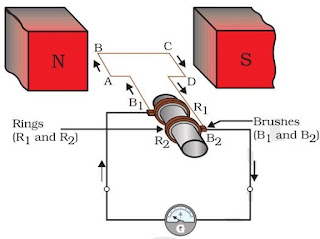
ELECTRIC GENERATOR :
The
structure of electric generator is similar to that of an electric motor. In
case of an electric generator a rectangular armature is placed within the
magnetic field of a permanent magnet. The armature is attached to wire and is
positioned in way that it can move around an axle. When the armature moves
within the magnetic field an electric current is induced. The direction of
induced current changes, when the armature crosses the halfway mark of its
rotation. Thus, the direction of current changes once in every rotation. Due to
this, the electric generator usually produces alternate current, i.e. AC. To
convert an AC generator into a DC generator, a split ring commutator is used.
This helps in producing direct current.

Electrical generator is based on the
principle of electromagnetic induction. It convert mechanical energy into electrical
energy.
Advantages of Alternate Current (AC) over
Direct Current (DC)
Electric
power can be transmitted to longer distances without much loss of energy.
Therefore cost of transmission is low.
In
India the frequency of AC is 50Hz. It means after every 1/100 second it changes
its direction.
In
our homes, the electric power supplied is of potential difference V = 220V and
frequency 50Hz.
It
consist of three wires :–
(1) Wire with red insulation cover – LIVE WIRE (POSITIVE) Live wire is at high
potential of 220V
(2) Wire with black insulation cover – NEUTRAL WIRE(NEGATIVE) Neutral wire is
at zero potential Therefore, the potential difference between the two is
220V.
(3) Wire with Green insulation cover – EARTH WIRE
It is connected to a copper plate deep in the earth near house.
The metallic body of the appliances is connected with the earth wire as a
safety measure.
Earth
wire provide a low resistance to the current hence any leakage of current to
the metallic body of the appliances, keep its potential equal to that of earth.
That means zero potential and the user is saved from severe electric shock.
Point to be noted in Domestic Circuit
(a) Each appliance has a separate switch of ON/OFF
(b) In order to provide equal potential difference to each appliance, they
should be connected parallel to each other. So that they can be operated at any
time.
Short Circuiting : Due to fault in the appliances
or damage in the insulation of two wires, the circuit will offer zero or negligible
resistance to the flow of current. Due to low resistance, large amount of
current will flow.
According to Joule’s law of heating effect , heat is produced in live wire
and produces spark, damaging the device and wiring.
Overloading : Overloading can be
caused by (1) Connecting too many appliances to a single socket or (2)
accidental rise in supply voltage if the total current drawn by the appliances
at a particular time exceeds the bearing capacity of that wire, it will get
heated up. This is known as overloading. Fuse a safety device can prevent the
circuit from overloading and short circuiting
No comments:
Post a Comment